Loading...
Loading...
Loading...
Loading...
Loading...
Loading...
Loading...
Loading...
Loading...
Loading...
Loading...
Loading...
Note: Double 4K - Skyport is formerly known as AGX710.
For S/N's 200+: Add support for Mavic 3E systems (912600 baud U-blox)
Add support for U-blox Gen-9 in PHX
Inhibit Skyport triggers when operating in non Command trigger mode
Update branding on configuration page
Use RTK data over Skyport for supported platforms and configurations
Additional logging of Skyport position data per session
Fix issue preventing DJI Pilot from updating photo counter
Update location of serial number tag to more standard id
Add missing band information for some D4k Variants (-10, -11, -98, etc)
Add XMP::Sentera tags to indicate the home takeoff location, altitude, and accuracy.
Default to assume forward facing flight on DJI Phantom/Mavic/Inspire systems.
Add support for different gimbal processors.
Enabled support for non-east facing flights.
Fixed issues with restarting sessions midflight.
Improved attitude stabilization.
Improved logging.
Fixed issue where above ground altitude was not written to image tags.
Fixed incorrect determination of terrain estimate.
Fixed issue that prevented gimbal firmware from updating.
Fixed issue on PHX RTK payloads recording incorrect terrain altitude.
Fixed incorrect terrain if AGX gimbal is launched prematurely.
Fix missing ACK packets for SCCP Protocol.
Updated exposure on select cameras for improved image analytics processing.
Added exposure information to exif and XMP:
Exif:ExposureBiasValue - EV Value target for the image.
XMP:Sentera:ExposureTarget - The value in the config file for EV (-12 to 12).
Added option to change which camera is used for overlap calculations:
Defaults to widest field of view camera.
Fixes for switching camera streams on AGX710 Skyport video.
Fix invalid session.txt altitude on PHX if camera reboots during launch
Set xmp IsNormalized=0 for better Pix4D support
Add fallback to platform GPS on RTK GPS dropout
AGX: Fix compatibility issues with newest M2XX firmware
AGX: Fix update issues on some AGX Platforms
Add system information to the diagnostics web page with firmware and hardware details
Fixed RTP video streams not starting properly
Fix camera hanging when AGX payloads did not detect a co-processor
config.yml files are now removed from the MicroSD card after being stored internally in the camera
This allows swapping cards between cameras without modifying their config files
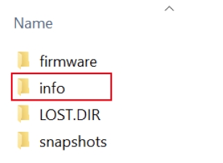
The current config and factory defaults are now found in the /info folder
To apply an update, copy the config.yml from the info folder to the root, modify the file, and reboot
If the config fails to load, it will be renamed to .failed along with a reason for the failure
Improved error messages to the user can be found on the camera web page
Information on the camera hardware is written to /info/hardware-config.yml on boot
Added capability for custom UV filters / aggressive CAC for tower inspections
AGX system/gimbal firmware now automatically updated to match camera firmware
Fix for custom (XXXXX-99) cameras video feeds
I2C fixed for 6601 to support light sensors
Loss of communication with the camera now display Communication Lost rather than SDCard missing
Improvements to LiveAnalytics for Stand Count
Added M200/M210 V2 Video Feed Support
Fix for the rare occurrence of corrupt images due to large thumbnail sizes
Added AGL Altitude to XMP.Camera.AboveGroundAltitude
Always write band information for cameras (removed option from the config file)
For S/N's 001 - 199: Update LEDs to be solid red/green = no go/go
AGX710: Fixed LiveNDVI view on Analytics cameras
Improved accuracy of LiveNDVI calculations for all sensors
For S/N's 200+: Add BLE support for setting overlap via Field Agent App
For S/N'S 200+: Update LED status codes to simpler Red/Green NoGo/Go
For S/N's 001 - 199: Added Analytics support
For S/N's 200+: Improved analytics processing time by a factor of 2
Enhanced RGB image quality and exposure settings.
Improved image metadata support for Pix4D.
New DISTANCE_3D trigger mode for vertical inspection applications.
AGX710 specific updates.
Enabled live analytics (stand and weed counts) for supported variants.
Fixed M200/M210 flight stability while connected to the Skyport.
Improved gimbal pointing performance.
AGX710: Fixed XMP Wavelength information generation for multispectral systems
AGX710: Camera will power down and close the sdcard on drone power off
AGX710: GPS Time used for timestamp rather than unreliable app time
Note: Existing customers will have to update SessionType to TIME_FIX to use this
AGX710: Altitude will be recorded as MSL instead of AGL in metadata files
AGX710: DJI Pilot widgets for selecting camera stream will reflect the actual imager types
Corrected an issue with Deere RTK systems that would report incorrect MSL altitudes
Improved robustness of communication with Deere RTK receivers
AGX-710: Fixed an issue with incorrect timestamps when no absolute time is received
Add support for John Deere RTK Systems (M210)
More visible errors on web page when SDcard is missing
Added age of corrections display to status webpage for RTK systems
Visible on RTK enabled systems only
Added satellite signal strength to ublox logging
Added further XMP tag support for Pix4D
Band width/frequencies and color transformation matrices
Add Z offset for antennae on RTK systems
Fixed a bug preventing quicktiles from PHXPro RTK systems
Add support for Sentera PHX RTK Revision 2 Payloads (Mavlink over UDP)
Add support for M200 Series gimbaled payloads (DJI PSDK)
Photo mode and Video clip recording from DJI Pilot is supported
Streaming Video, LiveNDVI, and Camera Switching available in DJI Pilot
FieldAgent Mobile support for image feedback
Add support for metadata from Honeywell Hg4940 series Inertial Navigation Systems
Add ability to set baud rate for all serial port protocols from the config file
Allows Mavlink interfaces to run at their default 57600 bps
Allow all protocols to interface over serial or UDP
DJI API Port (M100/A3) is currently not supported over serial
Fixes inability to start session on Omni-RTK Piksi Systems
New config.yml structure, old files will be automatically upgraded on boot
config.yml Version 1.3
Adds support for Sentera PHX RTK Camera Payloads
SourceType: MAVLINK_SBP
Fixes communication with M100/M600 platforms broken by newer firmware updates
Fixes incorrect setting for GPU governor on bootup
Fixed session start issues with Omni and PHX Pro platforms
Added support for Swift Piksi RTK GPS units on M100 systems
Enabled world file usage for DJI/Inspire systems
For best results, use an Inspire system with a NADIR Gimbal
Added iperf3 server to test connection quality to the camera
Increased precision of lat/long EXIF tags to allow for RTK precision
Auto ISO is now enabled for use on all cameras.
This will auto-adjust gain to a max shutter speed of 2.5ms
Decreased key-frame interval on video feed to improve performance in lossy datalinks
Added detailed payload attitude support for Sentera gimbals on Indago2 firmware >2.7.0
All platform types now record GPS accuracy and details in XMP or EXIF tags when the information is available.
Added support to enable/disable wifi access point from the config file (Requires installed wifi antennas)
SSID: Sentera_[PartNumber]_[SerialNumber]
ex. Sentera_21020-03_0003
Pass: [SerialNumber][SerialNumber]
ex. 00030003
Added improved web page interface
GPS position, status, and attitude data can now be monitored
Configuration files can be swapped
Popular config files can now be stored internally in the camera (or SDcard) and selected via the web interface.
Imagers now consistently take images in the same order, improving high overlap surveys
Fixed a bug that was preventing the info.txt file from being generated in some case
Fixed XMP import issues with newer versions of Pix4D
Improved behavior of the system during overheat conditions
Added support for FieldAgent™ ILS Analysis
Added thermal and CPU performance logs to the info folder to monitor thermal issues
Added Mavlink message logging
Added capability to disable CPU cores
If no firmware folder is present on the SDcard, an empty folder is created
GPS Latitude and Longitude Exif tags updated to be unsigned rationals
A missing SDcard will still allow the system to boot (but not start a session)
Improved capture rate while using XMP tags in images
Fixed a possible crash when capturing images at near the max rate of the camera
Added Support for Narrowband NDRE, NDVI, and RGB Filters
Copying firmware update files to the SDCard on MaxOSX now updates properly
Fixed bug preventing ILS over UDP from starting a session
Fix attitude in Ublox based systems (Phantom/Inspire Upgrades)
Disable Auto Antibanding for all imagers
Additional XMP and Exif tags are now written to jpeg images
pix4d.csv is no longer required to import into Pix4D, all camera parameters, GPS, and pose are contained in the image
Cameras with supported hardware now perform flat field corrections on the camera before saving the image
Omni systems can now control the EV Compensation and ISO in flight with OSD feedback
Onboard FFC is enabled for select Snapcam hardware
Improved timing repeatability across the board when triggering near the maximum camera rate
Thumbnails are not longer embedded in exif (they were not being used)
Light Sensor and GPS/RTK Precision data is now recorded to image-metadata.txt
Dji.csv log file now generated with information received from DJI autopilots
If the hardware-config partition is corrupt, a better log message is generated
Closing a session without a video feed will now complete successfully
Added CPU temperature and frequency logging to jpegs.csv
A3 Support over UDP works in DJI Simulator again
Added a new overlay to indicate the pitch and roll of the gimbal
A line with degree markers is shown at -90, 0, and 90 degrees absolute to help with inspection
Added a System Time packet to the ICD to allow fine tuning of time before and during a session
See ICD Documentation for more details
Many improvements to how the config.yml file is handled
The last known good config file is now saved in the camera and used if config.yml on the card is blank or missing
A factory config file can be set for the camera to use as a reference. This file is written out to the SDcard on boot
config.yml is always written to the SDCard on boot if the card is present. This allows the user to see what settings are loaded
Fixed a bug in the Still Session Ack Packet that was sending an incorrect ID
Fixed a bug where autopilots without attitude
Blank config files will no longer crash the camera
Added Hardware Configuration files containing Imager.confs
IMPORTANT: These will need to be loaded in after the firmware going forward from this version
System.info files now saved to image folders as well and imported into FieldAgent™.
LiveNDVI cameras report as NIR+ in ICD Status Packets
Fixed a bug where changing video feeds could cause the feed to crash
Added logging of RTK Relative Position to gps.csv
Increased readability of yellow GPS Status Icons (Darker Shade)
Fixed factor offset in gps.csv log file
Added GPS Status Overlay to video feed
Added Crosshairs to video feed
Added capability to disable individual OSD items
Added StartingZoomSteps config to start the camera zoomed in for factory focusing
Fixed a color mapping bug for LiveNDVI that was resulting in bad images
Added support for Ublox over UDP configuration for the OMNI platform
Added support for OMNI metadata using combined Ublox (Lat/Long/Height) and DJI (Yaw)
This mode is selected with Source Type: UBLOXP_DJI
Time Interval of < 1 second for triggers is now interpreted correctly
Fixed ICD for ImagerPreviewStream setup to correct an RGB/NDVI selection issue
ICD Status packets now report the correct imager type following the Sentera ICD.
Changed Height for Ublox to use hMSL rather than height above ellipsoid.
Fixed a gimbal lock issue when calculating image roll/pitch/yaw at a gimbal position of exactly 90
Occasionally, the config.yml on the SDcard can be erased. When this happens, the LED will remain blinking red and never go green.
To fix the boot issue, copy the backup file on the SDcard to config.yml replacing the bad one.
A3 GPS Detail packet parsing added to get MSL altitude and other useful parameters
Parsing of SBGC data for the Omni and M600 systems added
Source type for DJI and U_BLOX modes can now also be commanded
Fixed minor threading issues when opening and closing sessions frequently during a flight
Support for DJI-M100 platform added
Uses Lat/Long/Alt/Yaw/Flight Status from the SDK
Support for DJI-M600 platform added
Uses Lat/Long/Alt/Yaw/Time/Flight Status from the SDK
Added user adjustable autoexposure settings.
Can choose: frame-average, center-weighted, spot-metering
Added a picture taken OSD indicator to the upper right corner of the video stream
Camera Preview Setup packet form the ICD support is now added, with new fields appended for preview stream position and OSD enable/disable
Digital Camera Zoom now supported through the ICD
Session.txt support added offline QuickTiles
Overlap modes are supported as a trigger mode for the M100/600 platforms
Support added for Incident Light Sensors over UDP
The system will now only queue up to 5 triggers if it is flooded with trigger requests at a rate faster than it can handle (usually > 2Hz). Any trigger requests given after the queue has reached 5 will be ignored and logged as a failed trigger.
World projection files in PROCERUS mode (Kestral Autopilot / ICD) now use aircraft yaw when generating world files.
Terrain Elevation packets will now update the terrain estimate used for automatic overlap modes.
Improved error handling when the IMU is not present on the I2C bus
Auto Overlap Trigger Modes do not currently take into account the digital zoom level
Fix for Mavlink Altitude being reported as too low in the metadata files
Fix the RTP Header for Mpeg2 TS w/ RTP Headers
Fix for incorrect time being received over Mavlink packets
Fixed a crash when using Mpeg2_TS in very bright or very dark environments
Added Mpeg2 Transport Stream as an option for streaming video
New config options to support RTP/Raw for H264 and Mpeg2_TS
Config file can now control whether live ndvi is used or not for streaming video
FOV in the status packet is now set to the value found in the config.yml
IMU Attitude data added to imu.csv for testing
Fixed Yaw/Pitch/Roll data in image metadata for Kestral autopilots
Fixed timestamps in metadata for Kestral autopilots
Session.txt files now correctly generated for offline QuickTile in FieldAgent™
Fixed status update rate to match VCHeavy refresh
Change heading names in a number of log files to correctly reflect timestamp values
Added capability to set the EV and ISO in the config file
snapcam.sdp is now automatically recreated when specifying new port/IP address for the video
Added capability to disable/enable video streaming and recording
Added capability to set status/video packets to a multicast IP
Added 2 new GPS trigger modes, GPS Automatic Overlap, and Fixed Height Overlap
Fixed the video being mirrored compared to the vehicle and jpeg images
Fixed a crash that could occur when triggering during session initialization
Removed a comma from the ILS log header
Terrain and Altitude (0x0E Packet) Support Added
Session.txt to allow offline QuickTiles added
EPSG.txt file now generated in the base directory when creating world files
Updated support for new light sensor board (TCS34715)
Fixed a compatibility issue with the new ICD and old Kestral autopilots. There is now an option to use the older Revision R protocol for these systems.
Fixed a compatibility bug with session ACK and VCTouch preventing session starts
Added logging of system messages to /info/logs (record of last 10 boots)
Configuration data used to capture images is saved for each session in session.info
Incident Light Sensor Support Added
Session Start and Triggering Modes are now separate
Camera and file creation times are now set by the GPS or Autopilot when available
Periodic capture mode is available as a trigger mode
GPS Accuracy required to start a session in GPS_FIX mode can now be set
Session name conflicts no longer override data
Append session options from ICD will now work. If the same session name plus the append flag is set, images will be appended to the session.
The default behavior without the flag is to append ### to the end of the identical session name. eg if 'test' already exists and append is off, starting a new session with this name will result in the folder 'test001', then 'test_002', etc
Opening a session when one is already open will now work
If the session is already open with the same name, the command is ignored
If the session name is different, the current session is closed and a new one opens.
The camera will again listen for multicast packets for ICD commands.
Fixed an issue that would cause ICD packets to get cross when rapid commands were issued.
From this release onwards, version downgrades are allowed by default
Added an option to disable world file generation
Allow the user to set a fixed altitude for world file generation
Allow the user to set the GPS trigger distance
GPS.csv is now generated when using Ublox GPS
Allows customization of the IP and port numbers for the system components
Fixed a bug that was causing NIR image to be encoded in software causing excessive CPU usage
Initial support for Mavlink Added
Default Video Size changed to 1920x1080
Fixed missing busybox commands from build 0.3.0
Mavlink does not currently work with Mission Planner
2 Vehicles are detected, does not trigger
Configuration file added to allow user control of settings
External GPS Can now trigger images
Live Video Streaming during an active session is now enabled
Top/Bottom, PiP, and Fullscreen modes available
Projection files are now generated for each image
HTTP Server added to browse folders, latest image, and current session files
VC Touch "Snapshot" Button Support
Color Conversion from YUV to RGB fixed
Initial Release. This is the first official release and supports ONLY Kestral autopilots. Triggering must be done by the autopilot.
Kestral Autopilot Support Added
Initial Release
Does not currently import into FieldAgent™ (needs more CSV Files)
Note: Double 4K - Skyport is formerly known as AGX710.
At the bottom of this page, you'll find instructions and templates to help you use Pix4D with your Sentera Double 4K Sensor. Make sure to download the correct template for your sensor. Using the incorrect template will produce inaccurate results. If you are not sure what type of sensor you have, contact us at [email protected]. We will need the model and serial number located on the side of your sensor.
For RGB Imagery taken with the Sentera Double 4K Sensor, you can use the standard Ag RGB template already in Pix4D.
To perform calculations manually, use this document.
Sentera Sensors will capture images whenever they are powered on and their trigger conditions are met. This occurs whether you’re flying with FieldAgent Mobile, or any third party application.
There are 4 different modes for trigger conditions, based on overlap, altitude, distance and time values. You can switch between these modes by editing a text file on the sensor's SD card. We will cover how to do that later in this article.
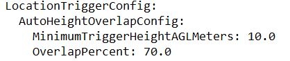
Green sensors are set to Auto Height Overlap by default. This mode uses two variables to know when to capture: 'Minimum Trigger Height Above Ground Level' and 'Overlap Percent'.
Minimum Height: When the sensor is below the minimum height, it will not capture images. The sensor's height is determined by its distance above the launch location. A low minimum height value helps reduce the amount of unwanted images taken on the ground and in transit, but it can prevent low altitude image capture. The default value is set to 10 meters. You can change this value to be between 0 and 200 meters.
Overlap: The sensor will capture an image once it has moved far enough to achieve the overlap value. The default value is 70%. You can change this value to between -600% and +90% overlap. If you have a Bluetooth enabled sensor, you are able to change the overlap percentage in the app.
Once your sensor reaches the minimum height and moves far enough to achieve the set overlap value, it will start capturing images.
This mode is similar to auto height overlap, except it requires you to specify what height your drone will be flying at. It uses two variables to know when to capture, 'Known Height Above Ground Level' and 'Overlap Percent'. This mode is useful when flying with Terrain Informed over a hilly field. Terrain Informed flight planning adjusts your drone's altitude to maintain the same distance above the field. By setting a known height above ground, your sensor is able to calculate when to take images, despite the differences in altitude.
Known Height: Set this value to the distance above ground your drone will be flying. Make sure this value matches the altitude of your flight plan. If you have an incorrect Known Height value, your sensor will not capture images with the set overlap value. You will need to update this setting every time you to plan to fly a different altitude. You can change this value to between 0 and 400 meters.
Overlap: The sensor will capture an image once it has moved far enough to achieve the overlap value. The default value is 80%, which is recommended to stitch your images. You can change this value to between -600% and +90% overlap. If you have a Bluetooth enabled sensor, you are able to change the overlap percentage in the app.
Once your sensor moves far enough to achieve the overlap value it will start capturing images. There is no minimum height which you sensor needs to reach.
Low altitude flights can be challenging with the overlap trigger modes. When your drone is low and moving fast, it can be limited by the sensor's shutter speed. This means that once your sensor is able to take another image it will have already moved too far to capture an image with the correct overlap. Flying at lower speeds will allow your sensor to capture the correct overlap.
This mode uses a distance variable to determine when to take an image. The default value is 10 meters, meaning your sensor will capture an image once your drone has moved 10 meters in any horizontal direction. You can change this value to between .5 and 1000 meters.
This mode uses a time variable to determine when to take an image. The default value is 5 seconds, meaning your sensor will capture an image once every 5 seconds. You can change this value to between 1 and 30 seconds.
You can switch between the 4 different trigger modes, as well as change the settings of each individual mode, by editing text files on the sensor's sd card. The Double 4K has a web interface which enables easy switching between different settings you have saved.
To change the trigger settings on your Sentera Double 4K Sensor:
Remove the microSD card from your Sentera Sensor and insert it into your PC.
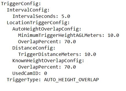
Browse to the file labeled Config.yml. Open it with Microsoft Notepad, Microsoft Word, or any other text editor.
Scroll to the bottom of the document and change the 'TriggerType' depending on which mode you want to use. The default value is AUTO_HEIGHT_OVERLAP.
Change the settings of each individual mode as needed. The setting for Known Height Above Ground Level can be found further up in the document.
Save the changes and insert the microSD card back into your sensor. The setting will remain unchanged until you manually change it or replace the microSD card.
The Double 4K has a web interface which allows you to switch between different configuration files you have saved. This is a quick way to change settings between flights.
Follow the instructions below for downloading and installing the firmware update for your Double 4K/AGX710 Sensor.
LED CODES: Solid Red - Sensor is booting, do not take-off Solid Green - Ready for flight Blinking Red - Error
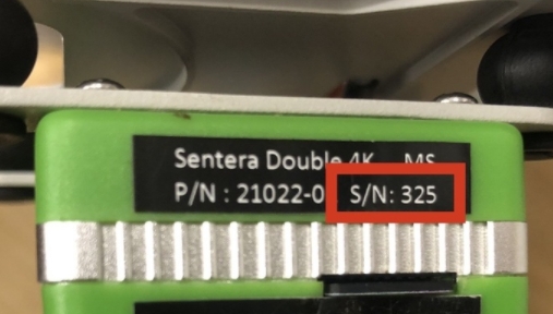
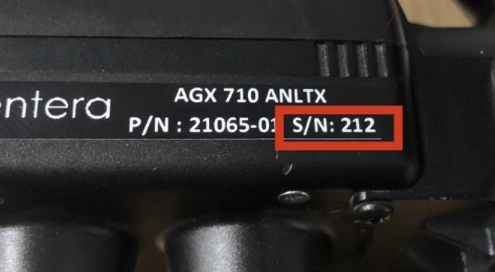
First, identify your product's serial number. The serial number is located on the sticker attached to the top or side of the sensor. See the images below for reference.
Select the appropriate firmware update below based on your serial number.
Note: Attempts to install the firmware on an incompatible product will fail, resulting in no changes to the performance or configuration of the device.
Serial numbers 199 or lower. This download is ONLY compatible with a Double 4K/AGX710 with a serial number 199 or lower:
Serial numbers 200 or higher. This download is ONLY compatible with a Double 4K/AGX710 with a serial number 200 or higher.
After downloading the firmware update file:
Remove the SD card from the Double 4K sensor and insert into a computer.
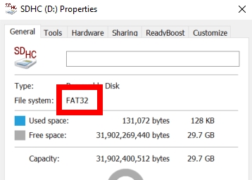
WARNING: If you are using a new SD Card, ensure the card is formatted to FAT32.
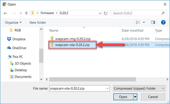
Copy the snapcam-ota-1.5.2.zip file for sensor 199 and under, and msM8996_sc-ota-1.5.2.zip file for serial numbers 200 and above, to the Firmware Folder on the SD card. (DO NOT unzip the file; copy the entire zip file to the folder.)
Insert the SD card into the sensor.
Power on the system.
Wait 15 minutes for the update to complete. The Double 4K will automatically reboot a few times and the LED will blink a variety of colors. This is normal.
Power off the system.
Remove the SD card from the sensor.
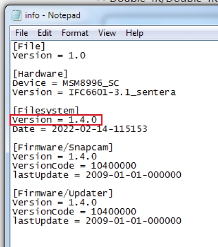
View the /info/info.txt file on the SD Card.
Verify that the Filesystem Version is the expected new version to confirm that the update was successfully applied. Example below:
Insert the SD card into the sensor. The update is complete.
For the NIR/Red Edge camera, we have the following combined spectral response:
Note that from this imager, we only use the Blue channel for NIR and the Red channel for Red. The green channel is discarded when performing index and band calculations.
If it is necessary to separate the channels further, we can use a system of equations to subtract out the effect of the out of band channels on each band. This calculation assumes that the incoming light is approximately uniform (which is the case with daylight). We also add the constraint that the power across each of the filtered bands is equal. This allows us to perform calculations across each of the color bands, even if the filter widths vary. This results in the following:
Red = -0.966DNblue + 1.000DNred NIR = 4.350DNblue - 0.286DNred
NDVI = (NIR - Red) / (NIR + Red)
For the NIR/Red Edge camera, we have the following combined spectral response:
Note that from this imager, we only use the Blue channel for NIR and the Red channel for Red Edge. The green channel is discarded when performing index and band calculations.
If our light source has smooth power across our wavelengths of interest, we can subtract out the us of band wavelengths in the NIR and Red Edge portions via the following:
RedEdge = -0.956*DNblue + 1.000*DNred NIR = 2.426*DNblue - 0.341*DNred
NDRE = (NIR - RedEdge) / (NIR + RedEdge)
User Guide for D4K Sensor
User Guide for the Config.yml file in order to setup custom configuration
Link to download the Double 4K CAD assembly.
This document describes the NDVI and NDRE calculations for the Double 4K (D4K) Multispectral camera.
The D4K Multispectral camera is a bit different than other cameras, since each band must be normalized to each other before indices that use both cameras are calculated.
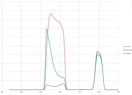
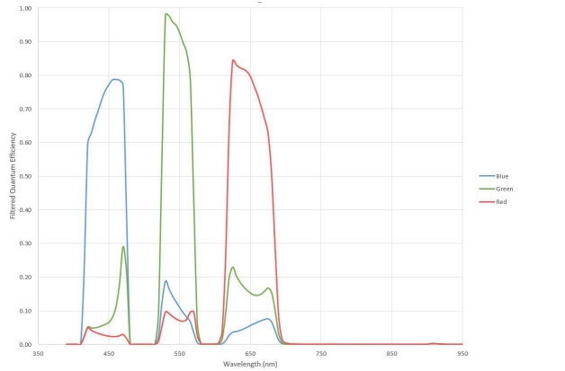
For the RGB side of the camera, the stacked filters result in the following spectral response, as shown in Figure 1:
In Figure 1, red/green/blue correspond to channels of the resulting jpeg image. Note that there is some cross talk between the channels. That is, the blue channel has primarily blue wavelengths, but also has small contributions from the green and red wavelengths as well.
If it is necessary to separate the channels further, we can use a system of equations to subtract out the effect of the out of band channels on each band. This calculation assumes that the incoming light is approximately uniform (which is the case with daylight). We also add the constraint that the power across each of the filtered bands is equal. This allows us to perform calculations across each of the color bands, even if the filter widths vary.
This results in the following:
DN [color] = digital number of that band (from the jpeg)
[color] = Corrected color after subtracting out of band colors
Blue = 1.377DNblue - 0.182DNGreen - 0.061DNRed
Green = -0.199DNblue + 1.420DNGreen - 0.329DNRed
Red = -0.034DNblue - 0.110DNGreen + 1.150*DNRed
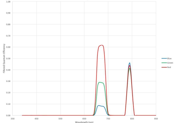
For the NIR/Red Edge camera, we have the following combined spectral response, as shown in Figure 2:
Note that from this imager, we only use the Blue channel for NIR and the Red channel for Red Edge. The green channel is discarded when performing index and band calculations. This is because there is not any additional useful information in the green band that isn't already captured by the blue and red bands.
Like the RGB method above (and subject to the same restrictions), we can subtract the out of band channels in the NIR and Red Edge portions via the following:
RedEdge = -0.956DNblue + 1.000DNred NIR = 2.426DNblue - 0.341DNred
When attempting to calculate indices that use both cameras, both the camera settings and the normalization factors used in the band math equations need to be considered during any index computations you may make.
You will first have to normalize each of your images for the total exposure opportunity. This will allow images with differing ISO and exposure times to be compared properly.
DN = Digital Number
Gain = ISO / 100 [Exif Tag]
Shutter = Shutter time in seconds [ Exif Tag]
ExposureOpportunity = DN / ( Gain * Shutter )
The normalization values for each band separation matrix were chosen independently for each camera to keep 8-bit values in their proper ranges (typically 0-255). A normalization value of 1/750 was used for RGB, and 1/277.7 was used for RedEdge. This means that a step increase in RGB values implies a 2.7x step in the RedEdge values. So, if you want to compute indices that use both cameras you must consider our band math gains. This is done after the bands are separated using the above system of equations.
So, you end up with the following:
NDVI = (2.700 * NIR_2 - Red_1) / (2.700 * NIR_2 + Red_1)
NDRE = (NIR_2 - RedEdge_2) / (NIR_2 + RedEdge_2)
Frequently Asked Questions
Note: Double 4K - Skyport is formerly known as AGX710.
First, confirm that you are using a MicroSD Card of the correct size and speed. Speed Specifications:
We recommend using a class 3 (U3 ~ 100mb/s) card
Maximum Card Size Specifications:
Single and Quad Sensors = 32 GB
Double 4K and Skyport = 64 GB
Determining the Format of your MicroSD Card
All SD Cards used in Sentera Sensors, must be in FAT32 format. To determine the current format of your MicroSD Card:
Insert the MicroSD card into a computer
Locate the MicroSD card in a finder window.
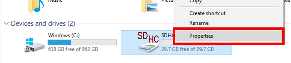
Right click and select properties as shown below.
Check the file system for "FAT32" as shown below.
If your MicroSD Card is already formatted to FAT32, move onto the next section, Using your FAT32 MicroSD Card. In addition, If your SD Card is not formatted to FAT32, follow the instructions detailed in the last section, Formatting an SD Card to FAT32. Using your FAT32
Insert your SD Card into your Sensor and if applicable, install your sensor onto your aircraft.
Power on the aircraft. The Sensor will write the necessary files to the card.
For the Sentera Single Sensor you will see Green, Yellow, and Red LED's. Please wait until the Red LED turns off.
For the Double 4K Sensor or Skyport you will need to wait until you have a solid Green LED.
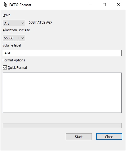
Formatting an SD Card to FAT32 If your SD Card is not formatted to FAT32, you will need to format the card using the tool below as Windows does not support the format natively.
Note: Windows might not download it when clicking on the link as it will say its suspicious, have windows download it anyway.
Software download link:
Before using the FAT32 Formatter Tool copy it to your Desktop, close Windows Explorer, then launch FAT32 Formatter.
Allocation Size for MicroSD Cards When using the FAT32 Formatter Tool, set it to the appropriate allocation size based on card storage.
16 GB Cards = 16384
32 GB Cards = 32768
64 GB Cards = 65536
You can now insert the newly formatted MicroSD Card in to the Sensor and power on the aircraft. The Sensor will write the necessary files to the card. Make sure you power on the sensor for about 5 minutes with the microsd card in the sensor.
For the Sentera Single Sensor you will see Green, Yellow, and Red LEDs. Please wait until the Red LED turns off.
For the Double 4K Sensor or Skyport you will need to wait until you have a solid Green LED. Typically, you will want to test this outside in order to get a Green LED, i.e., the sensor needs GPS and needs direct line of sight with the sky.

Below are instructions for accessing and using the diagnostics web pages for the Double 4K series cameras. These pages provide access to the following camera features and options, which are not available elsewhere:
Camera status and control
Remote SD card browsing
Most recent image previews
Firmware updating
Manually starting sessions and triggering the camera.
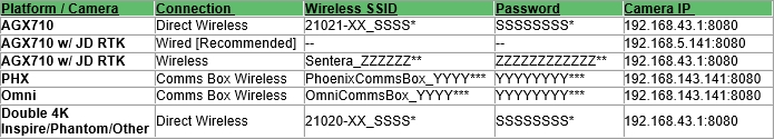
Depending on your system’s platform and camera, your IP address and connection method may vary. See the table below to identify your camera’s IP address.
XX – Depends on the model of camera
*SSSS – The serial number of the camera (i.e., 0025)
*SSSSSSSS – The serial number of the camera repeated twice (i.e., 00250025)
***YYYY – The serial number of the system (i.e., 0002)
***YYYYYYYY – The serial number of the system repeated twice (i.e., 00020002)
**ZZZZZZ – The serial number of the system (i.e., 001122)
**ZZZZZZZZZZZZ – The serial number of the system repeated twice (i.e., 001122001122)
Power on the system and wait for the bottom LED on the camera to turn solid or blinking green.
Connect to the camera via a wired or wireless connection (see table above).
For example, for an Inspire Double 4K with serial number 42, connect using:
SSID: 21020-02_0042
Password: 00420042
3. Open a web browser and navigate to the Double 4K Setup Page.
Use the IP listed in the table for your system.
For example, for the Inspire Double 4K, use: http://192.168.43.1:8080/
4. If you are connected properly, the main Double 4K overview page will appear.
Connecting to the Double 4K camera will pull up the homepage. You can access additional pages from the left-hand menu. If you don’t see this list of pages, click the three lines in the upper left corner of the web page to expand the menu.
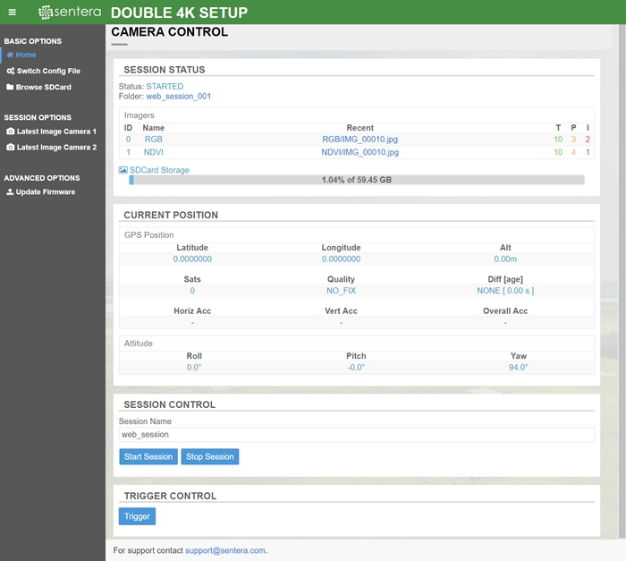
Homepage
On the homepage, you’ll find an overview of your current camera configuration, SD card capacity, and session status. You’ll also find controls to manually start and stop sessions and trigger images.
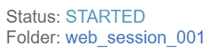
Session Status
Status: Indicates the state of the camera session. Typical values are:
IDLE: The camera is waiting for a session to start. No images will be taken.
STARTING: The camera is initializing.
STARTED: The camera is ready to take images.
STOPPING: The camera session is shutting down.
Folder: Displays the name of the active session. Click on the session name to view the contents of the session folder.
Imagers:
ID: The internal ID of the imager.
Name: The name of the folder where the imagers' images are stored.
Recent: A link to the most recent image taken by this camera.
T: The number of images taken this session.
P: The number of pending images (requested, but no captures) this session.
I: The number of ignored trigger requests.
Current Position
Latitude/Longitude/Alt: The current latitude, longitude, and altitude taken from the autopilot or connected GPS unit.
Sats: The number of satellites used to compute the current position.
Quality: The relative quality of the GPS Fix.
NO_FIX: Not enough satellites are visible to obtain a position fix.
ACQUIRING_FIX: Some satellites are found, but not enough to get a position.
LOW_ACCURACY_FIX: Position is found, but the accuracy is very low (typically > 5 meters)
ACCURATE_FIX: Position is determined (<5m accuracy). In some modes, this triggers a session start.
HIGH_ACCURACY_FIX: Highly accuracy fix (typically on RTK systems and <1m).
Diff: The status of the differential GPS corrections (typically used in RTK systems). RTK systems display in seconds the age of the last RTK correction.
NONE: Differential corrections are not used.
DGPS_FIX: Satellite-based corrections are being used.
RTK_FLOAT_FIX: RTK Float solution is being used.
RTK_INTEGER_FIX: RTK Integer solution is being used (highest available accuracy).
Roll/Pitch/Yaw: The current attitude of the camera in North-East-Down coordinates.
SD Card Storage: The amount of space remaining on the installed SD card.
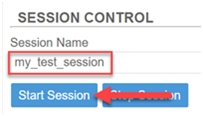
Session Control
If a session is not running, you can name and start a new session using Session Control. Type the name of the session in the text box, and then click the Start Session button. The status at the top of the screen will reflect the new session name and status after a few seconds.
To stop an active session from taking pictures, use the Stop Session button.
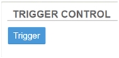
Trigger Control
When a session is active, you can click the Trigger button to take an image.
Note: In order to trigger an image, a session must be actively running.
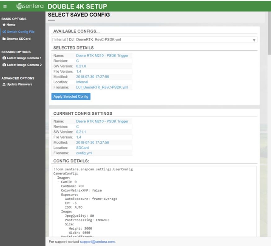
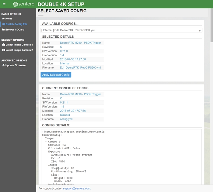
Switch Config File
/switch_config
Under Switch Config File, you can change the camera configuration to pre-saved files located on either the SD card or the internal memory.
To change the camera configuration:
Select the configuration file you would like to use from the drop-down menu.
[Internal] means configurations are stored on the camera.
[SDCard] means they are stored on the SD card and can be modified.
After you select a file, the details will appear in the Selected Details section.
Confirm that the file is correct, and then click the Apply button to load the configuration onto the SD card.
To confirm that the changes have been made, wait 5 seconds, and then examine the Current Config Settings and Config Details section to make sure they have been updated.
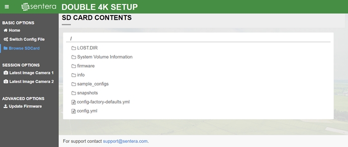
Browse SDCard
/sdcard?path=[path]
Under Browse SDCard, you can browse and download contents of the SD card.
To skip to a particular folder on the SD card without clicking through each directory, enter the path you wish to browse to in the path argument of the URL. For example, to skip to the web_session folder of the SD card, use the following: /sdcard?path=/snapshots/web_session
/last_img?camera=1/2
Under Latest Image Camera 1/2, you can view the most recent image captured by the camera. The page will automatically refresh every 5 seconds and continue to display the most recently captured image.
Note: This page is only available when a session is active.
/firmware_update
Under Update Firmware, you can update firmware from the web interface. See the Updating the Firmware section below for instructions.
In some cases, you may want to manually trigger the camera via the web interface. This allows you to test images on the ground or in a lab environment where lack of GPS may prevent the camera from starting a recording session.
To manually trigger the camera:
Connect to the Double 4K diagnostics page using the procedure at the top of this document.
Navigate to Home.
Check to make sure a session is active by looking at the top of the homepage.
If a session is active, the status should be STARTED.
If no session is active, start a session. Go to the Session Control section, enter a session name, and click Start Session.
4. Find the Trigger Control session and click Trigger.
The camera will take an image each time you press the Trigger button.
You can queue up multiple triggers by clicking the button multiple times in a row.
If the trigger button is grayed out, make sure a session is running.
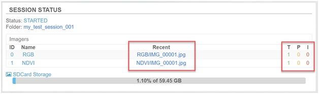
5. Check the Session Status section to verify the camera has taken an image.
The Recent link will update to show the most recent image.
The Taken (T) count will also increment for both imagers.
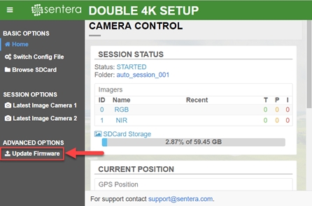
Connect to the Double 4K diagnostics page using the procedure at the top of this document.
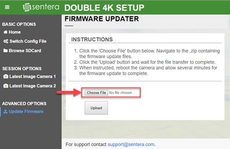
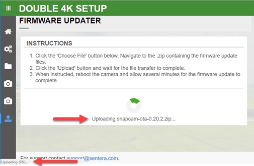
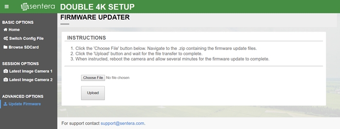
Click on the Update Firmware button on the main web page.
Click the Choose File Button and select the Snapcam-ota-*.zip packet provided in the updater.
Click Upload.
The screen will change to an upload in progress window.
Monitor the bottom of your web browser to see the upload progress (see image below).
Wait for the update to finish uploading.
When the update completes successfully, you will see a Firmware File Successfully Uploaded message.
The camera will reboot a few times while it applies the hardware configuration and update file.
During this time, the light will rapidly blink red and the camera may restart.
When the update is complete, the bottom LED will remain solid green.
Ensure the bottom LED on the camera is solid green for ~20 seconds.
If it is blinking red, the update is still being applied. Wait for it to finish.
To verify the update has installed, follow the Checking Firmware Versions procedure below.
IMPORTANT: If you are connected via a wireless network, you will have to reconnect the camera after it reboots and before verifying the update below.
To verify that the camera has applied the firmware update:
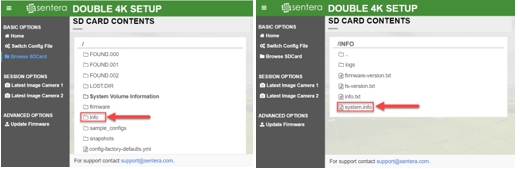
1. Connect to the Double 4K diagnostics page using the procedure at the top of this document. 2. Click on the Browse SDCard menu option.
3. Using the web based file browser, navigate to /info/ system.info.
4. Verify that the version in the Release Info section matches the version that was applied.
Note : Double 4K - Skyport is formerly known as AGX710.
A mechanical model of the Double 4k sensor is available for download in STEP file format.
Sentera Double 4K CAD Model (.step)
The following tables list pin descriptions of the camera connectors. All 3.3V UART and 3.3V I2C interfaces are not 5V tolerant. For additional detail on camera interfaces, contact Sentera. J10 is a USB 3.0 connector and is only used by Sentera during development and testing.
J3 - Main Power and Signals
1
VCC
PWR
Camera power input (6V to 26V).
2
GND
PWR
Camera power input (6V to 26V).
3
(3V3) TXD
O
3.3V UART bus.
4
(3V3) RXD
I
3.3V UART bus.
5
VCC_3V3
PWR
3.3V switched power output - selectable upon request.
6
(3V3)SDA
I/O
3.3V I2C bus.
7
(3V3)SCL
I/O
3.3V I2C bus.
8
EN_A
PWR
3.3V switched power output (with pin 5) - selectable upon request.
9
GPIO_B2
I/O
Reserved.
10
RSVD
N/A
Reserved.
Connector: BM10B-GHS-TBT
J4 - Ethernet Pin Descriptions
1
TD0P
Transmit Data+ or BiDirectional.
2
TD0N
Transmit Data- or BiDirectional.
3
TD1P
Receive Data+ or BiDirectional.
4
TD1N
Receive Data- or BiDirectional.
5
TD2P
Not connected or BiDirectional.
6
TD2N
Not connected or BiDirectional.
7
TD3P
Not connected or BiDirectional.
8
TD3N
Not connected or BiDirectional.
Connector: BM10B-GHS-TBT
J5 - Auxiliary Power and Signals
1
GND
PWR
3.3V power output.
2
VCC_3V3
PWR
3.3V power output
3
EN_B
PWR
Regulated 5V power output, up to 500mA.
4
VCC_5V0
PWR
Regulated 5V power output, up to 500mA.
5
(3V3)SCL
I/O
3.3V I2C bus.
6
(3V3)SDA
I/O
3.3V I2C bus.
7
(3V3)RX1
I
3.3V UART bus.
8
(3V3)TX1
O
3.3V UART b
9
(3V3) RXD
I
3.3V UART bus.
10
(3V3) TXD
O
3.3V UART bus
11
GND
PWR
Camera power input (6V to 26V).
12
VCC
PWR
Camera power input (6V to 26V).
Connector: BM12B-GHS-TBT
The camera is able to auto-negotiate the Ethernet speed. Therefore, only four pins are required for slower 10Base-T or 100Base-T speeds. All eight pins are required for communication at a 1000Base-T speed.
Typical users will choose either J3 OR J5 depending on their specific installation requirements. Many of the signals are shared between J3 and J5 including the primary input power, UART, and I2C connections. The following connections are shared between the connectors:
Camera power input (6V to 26V): VCC & GND
J3: pins 1-2
J5: pins 11-12
3.3V UART bus: RXD & TXD
J3: pins 3-4
J5: pins 9-10
3.3V I2C bus: SCL & SDA
J3: pins 6-7
J5: pins 5-6
The camera contains two indicators for providing feedback on the camera’s operation. The indicator closest to the top of the camera identifies camera Power, while the indicator closest to the bottom of the camera identifies camera Status. Each display indicator contains a set of LEDs: a green LED and a red LED .
Once the camera is powered, both the green and red LED of the Power indicator will be on. The status indicator LED uses both green and red LED to indicate the current state of the system, per the following diagrams.
Initialization Operation : The camera is initializing its components and performing startup functions. State Time : Camera initialization can take up to 60 seconds. Transition : The camera transitions to the idle state immediately after the initialization of all camera components is completed. Status Indicator : Off or Flashing red.
Idle Operation : The camera is waiting to start a session. Criteria for starting a session are based on configuration setting – see section Operation Modes. State Time : The state occurs indefinitely until criteria are met for starting the session. Transition : The camera transitions to the active state once a session is started. Transitions from the idle to active state can take up to 20 seconds. Status Indicator : Solid green.
Active Operation : The camera is able to take pictures and log these pictures along with metadata to the SD card. This state cannot be entered if the SDcard is missing or corrupt. State Time : This state occurs indefinitely until criteria are met for closing the session. Transition : Transition to the idle state occurs if the session is closed. Status Indicator : Flashing green.