FieldAgent Web User Guide
Introduction
Welcome to the Sentera FieldAgent Web App User Guide. This user guide is designed to provide documentation for people who will use FieldAgent on a professional basis. This document is designed to be read by any user of FieldAgent, as most users will have access to the features documented here. This guide is targeted to new users with an understanding of digital agricultural platforms.
Login and Passwords
The following section describes how to login and maintain passwords.
System Requirements
FieldAgent Web App must meet these system requirements:
High speed internet connection.
An Internet browser, such as Chrome, Firefox, Safari, Edge, Opera.
An operating system, such as Windows, Mac OS, Android, iOS.
Login Procedure
To log into FieldAgent Web App, follow the following steps:
Open the web browser.
Navigate to: https://fieldagent.sentera.com/.
Sign Out of FieldAgent
Users of FieldAgent Web App should completely sign out at the end of the session to ensure data privacy and integrity. This section describes how to properly sign out.
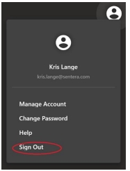
Click Account icon at the top right side of the screen and click Sign Out, as shown in Figure 1.
System Selections
Users of FieldAgent Web App can view and update various system selections by clicking the gear icon at the left side of the window, as shown in Figure 2.

Language
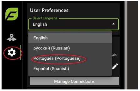
Users of FieldAgent Web App can change the update the app to display in their desired language. To select a language:
Click the gear icon at the top of the menu.
Select the language from the dropdown, as shown in Figure 3.
Units of Measurement
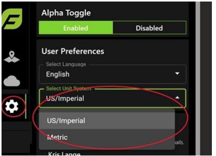
Users of FieldAgent Web App can update the Web app to different units of measurement. To select a different measurement:
Click the gear icon at the top of the menu.
Select the prefered unit of measurement, as shown in Figure 4.
Manage Account
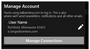
Users of FieldAgent Web App can manage the account by selecting the pencil icon or Manage Account button, as shown in Figure 5. If you have access to manage accounts, click Manage Connections and update the information.
Billing
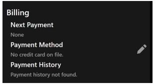
Users of FieldAgent Web App, who have access, can manage billing details by selecting the pencil icon in the Billing section, as shown in Figure 6.
Subscriptions
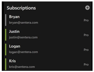
Users of FieldAgent Web App can switch between the fields they are subscribed to selecting a different subscription from within the Subscription area, as shown in Figure 7.
Field Navigation
This section describes how to navigate the FieldAgent Web App
Navigate Field List
FieldAgent Web App lists all fields that are available under your User ID.
Select a field. The menu changes and the field displays, as shown in Figure 8.
![]() Note: Select Sort By or Year Planted to narrow the search.
Note: Select Sort By or Year Planted to narrow the search.
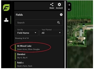
Once the field is selected, the menu changes and the field displays.
Click the back arrow at the top of the menu to go back to the previous menu.
Navigate Multi Level Org Fields
For organizations that have multiple levels or hierarchy, there are two ways to search for the field you want to view. The following section describes those options.
Use Menu Hierarchy
To search using the hierarchy menu to view all of the fields under a particular organization:
Select the dropdown menu from the upper right corner of the screen, next to the organization name to expand the organization’s field list, as shown in Figure 9.
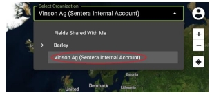
Continue to select arrows until the correct field is found.
Select the field.
Search
To search using the Search field:
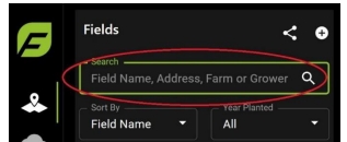
Enter the name, address, farm, or grower of the field, as shown in Figure 10.
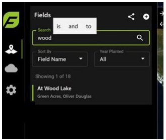
As you start to type the name of the field, it starts to auto-populate the list, as shown in Figure 11. Or you can select the field from the list of fields.
Select a field.
Navigate the Fields Menu
This section describes how to navigate the Fields menu, which includes the Shape Annotations and Map Layers.
Create Shapes in Zones
Zones allow the user to turn on and off field boundaries, create additional boundaries, or add shapes to the field.
To turn on or off the field boundary:
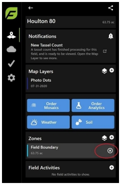
Select the field boundary in the Zones area, as shown in Figure 12.
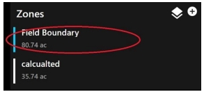
Click the”x” to turn the Field Boundary on and off, as shown in Figure 13.
To add a shape to a field:
Select the field, then in the Zones area click the plus icon + icon to add a shape, as shown in Figure 14. The shapes menu displays.

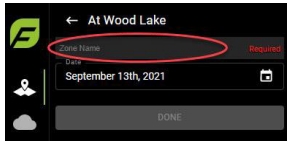
Enter the name the shape, as shown in Figure 15.
Click a polygon shape from the tools menu from the right side of the screen, as shown in Figure 16.

Use the cross hairs to draw the shape, as shown in Figure 17. Enter the name in the Zone Name area.

Click Done when complete. The new layer displays in Zones, as shown in Figure 18

To edit the field boundary:
Select the field, then in the Zones area click Field Boundary, the click the Edit icon, as shown in Figure 19.

Edit any details you want for the field such as name or address. Click and drag the field boundary to edit the shape, as shown in Figure 20.
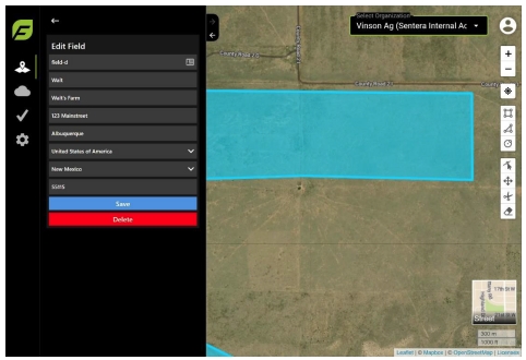
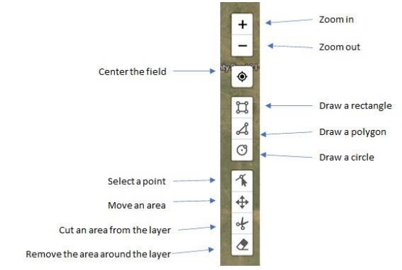
Use the toolbar to adjust the field, as shown in Figure 21.
Click Finish next to the Edit icon, and then click Done when the changes are complete, as shown in Figure 22.
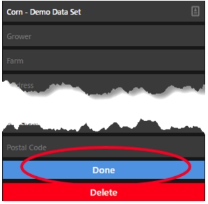
To delete a field:
Select the field, then in the Zones area click Field Boundary, as shown in Figure 23.

Click the Edit icon on the toolbar on the right hand side of screen, then click Delete at the bottom of the Edit Zones menu, as shown in Figure 24.
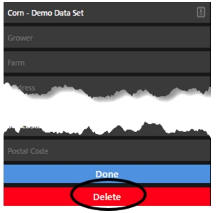
Click Delete to confirm the field deletion, as shown in Figure 25
Importing Images into FieldAgent Web
Once a field has been created, or already exists in FieldAgent Web App, images can be imported directly into the website instead of through the desktop.
Select the field from the list of Fields that will you have images to import.
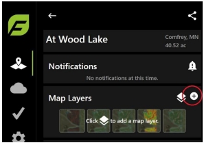
From the field menu, select the + sign next to Map Layers, as shown in Figure 26.
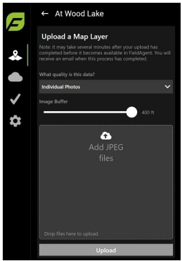
Select the quality of data and then click Add JPEG files to select the images to import, as shown in Figure 27.
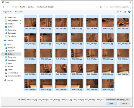
Browse to the folder that contains the images. Select the images to be imported into FieldAgent Web. Click Open, as shown in Figure 28. Repeat these steps for each folder that is being imported.
![]() Note: This process is slightly different than FieldAgent Desktop where images are imported at the folder level.
Note: This process is slightly different than FieldAgent Desktop where images are imported at the folder level.
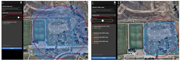
Using the Image Buffer slide bar to adjust the buffer to include only those images that fit within the Field Boundary, as shown in Figure 29.
Click Upload in the bottom left menu, as shown in Figure 30. The images will start to upload to FieldAgent Web App.
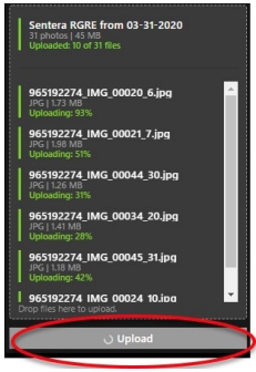
Once the upload has completed, the following confirmation prompt will display, as shown in Figure 31. An email confirmation will be sent shortly.

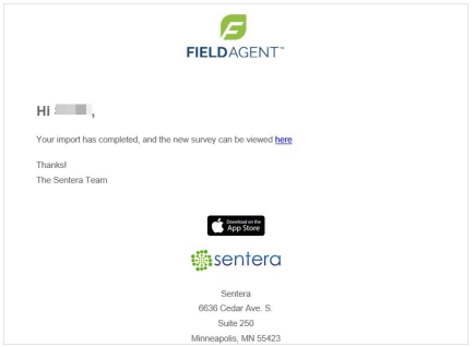
Once the email is received, as shown in Figure 32, you will be able to view the individual images that were imported.
Notifications
Based on your Field Activity details such as entering planting data, FieldAgent displays Notifications to help prepare, prevent, and understand potential hazards for the field. A notifications indicator will appear next to the field name, as shown in Figure 33. Notifications alert to events such as plant stress or hail damage, allowing you to gather information for insurance purposes or plan a drone flight.
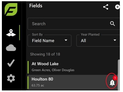
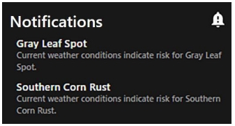
Click the field to view the relevant notifications, as shown in Figure 34. The notifications are dependent upon how accurate the information is in activity details.
Turn Off/On Notifications
To turn off and on disease, weather, field, NDVI, growth stage, and other notifications within FieldAgent Web:
Log into your account at https://fieldagent.sentera.com/.
Click the Settings gear icon.
Check or uncheck the items from the Notification Preferences area, as shown Figure 34.
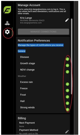
Check the items from in the Notifications to turn them back on during the next planting season.
Map Layers
Map Layers allow the user to view images imported into FieldAgent Web App from the Sensor, Drone, or Satellite data. This section describes how to navigate the map layers.
Select the field, then in the Map Layers area click the Layers icon to view map layers, as shown in Figure 36. The Add Map Layers window displays.
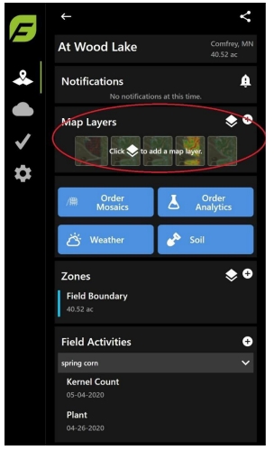
Select the Surveys, Satellite, and/or Flight Logs icon(s) to view the map layers, as shown in Figure 37. The Surveys icon displays images captured by the drone, the Satellite icon displays the satellite imagery, and the Flight Logs icon displays the flight paths flown.
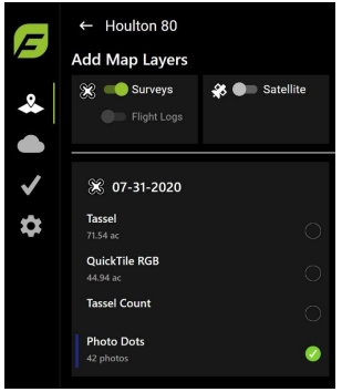
Scroll to the date of the survey to view and then select the images, as shown in Figure 38.
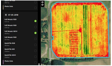
Scroll to view Satellite data, as shown in Figure 39.
![]() Note: Satellite images are not taken every day and are not always usable due to cloud cover. The percentage amount next to the sun icon displays the precentage of sun on that day. In this case it is 99%.
Note: Satellite images are not taken every day and are not always usable due to cloud cover. The percentage amount next to the sun icon displays the precentage of sun on that day. In this case it is 99%.
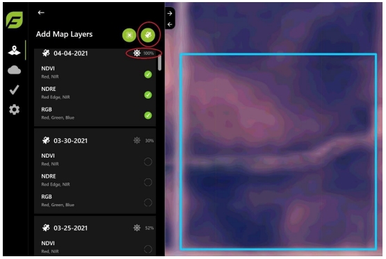
NDVI ToolBox
The NDVI ToolBox allows the user to adjust how the data is viewed in the NDVI or NDRE images. This section describes how to adjust the images.
Drone Images
The NDVI ToolBox provides a number of details and options to work with the data from a selected image. This section describes how to view the drone images.
Once the images are selected from the Map Layers, scroll to the top of the menu and click the back arrow, as shown in Figure 40.

Select an item in Map Layers to display, as shown in Figure 41.
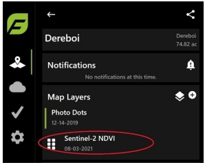
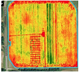
To select the number of color bins to display, use the Colorization & Stats slider, as shown in Figure 43. The default is 20, but can be changed from 1 to 20. The slide bar allows the user to remove data that is not relavant to the image.

Observe the map layer changes, depending upon what is selected, as shown in Figure 43.
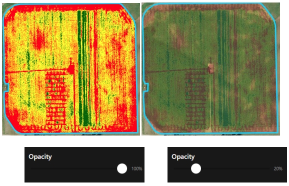
Use the Opacity slider to change the ability to view the background satellite imagery through the NDVI or NDRE image, as shown in Figure 44.
Select the Reference Date, Units of Measure, and Growing Degree-Days if weather data is available for the date range of the flight, as shown in Figure 45.
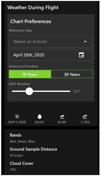
Definitions of icons include:
![]() Growing Degree-Day: A measure of heat accumulation used by farmers to predict when a crop will reach maturity.
Growing Degree-Day: A measure of heat accumulation used by farmers to predict when a crop will reach maturity.
![]() Cumulative Rainfall: Combined amount of total rainfall for any given period.
Cumulative Rainfall: Combined amount of total rainfall for any given period.
![]() 30 Year Average Rainfall: Amount of total rainfall a 30-year period.
30 Year Average Rainfall: Amount of total rainfall a 30-year period.
![]() Rainfall Difference Percent: Calculated percentage deviation (+ or -) for a particular time.
Rainfall Difference Percent: Calculated percentage deviation (+ or -) for a particular time.
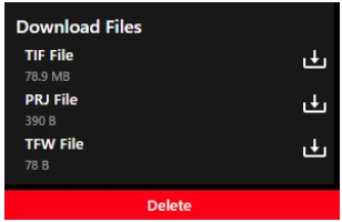
Click the arrow to download the displayed image, as shown in Figure 46.
View Sentinel-2 Satellite Images
The following section describes how to view Sentinel-2 Satellite images:
Once the images are selected from Map Layers, scroll to the top of the menu and click the back arrow, as shown in Figure 47.

Select the item in Map Layers. The map layer displays, as shown in Figure 48.
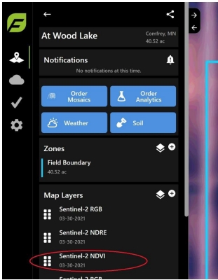
Slide the Sentinel Colorization & Stats slider to chose the number of color bins to display, as shown in Figure 49. The default is 20 and can be changed from 1 to 20. The slider bar allows the user to remove data that is not relavant to the image.

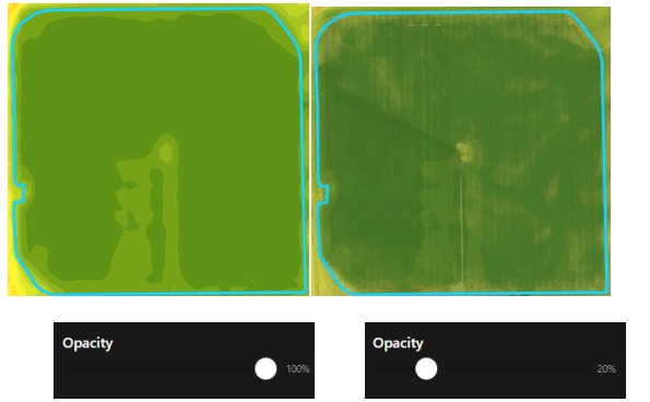
Slide the Opacity slider to change the view to see the background satellite imagery through the NDVI or NDRE image, as shown in Figure 50.
Select the Reference Date, Units of Measure, and Growing Degree-Days if weather data is available for the date range of the flight, as shown in Figure 51.
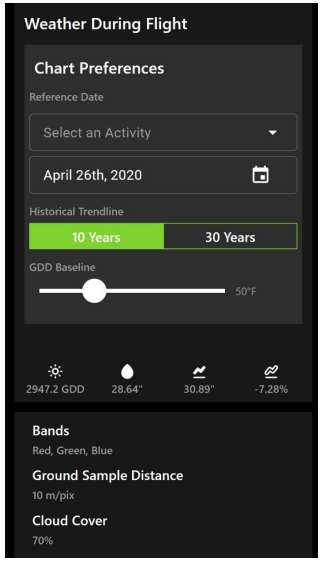
Definitions of icons include:
![]() Growing Degree-Day: A measure of heat accumulation used by farmers to predict when a crop will reach maturity.
Growing Degree-Day: A measure of heat accumulation used by farmers to predict when a crop will reach maturity.
![]() Cumulative Rainfall: Combined amount of total rainfall for any given period.
Cumulative Rainfall: Combined amount of total rainfall for any given period.
![]() 30 Year Average Rainfall: Amount of total rainfall a 30-year period.
30 Year Average Rainfall: Amount of total rainfall a 30-year period.
![]() Rainfall Difference Percent: Calculated percentage deviation (+ or -) for a particular time.
Rainfall Difference Percent: Calculated percentage deviation (+ or -) for a particular time.
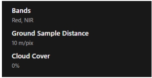
Review details about the image at the end of the Satellite NDVI ToolBox menu, as shown in Figure 52. Include Bands, the GSD, and Percent of Cloud Coverage that day.
How to Order Analytics
Plant and Weed Population Maps provide detail on the rate of emergence and weed location. With emergence data one can determine a number of items relating to seed effectiveness to yield estimation.
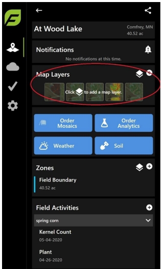
Select a field, then from the Map Layers area, click the layers icon, as shown in Figure 53, to view map layers. The Add Map Layers window displays.
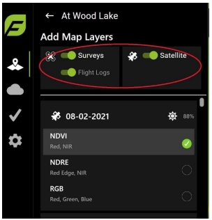
Select the Drone, Satellite, and/or Flight Logs icon(s) to view the map layers, as shown in Figure 54. The Drone icon displays images captured by the drone, the Satellite icon displays the satellite imagery, and the Flight Logs icon displays the fight path taken.
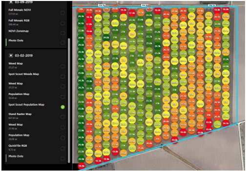
Scroll to the date of the survey to view and then select the images, as shown in Figure 55. The population per acre is displayed both numerically and visually.
To complete a more detailed analysis, click back arrow at the top of the menu, as shown in Figure 56.

From the Map Layers menu, select Spot Scout Population Map, as shown in Figure 57.

The details of the Spot Scout Population Map are listed in the menu, as shown in Figure 58.

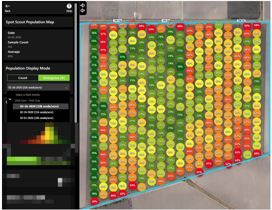
To change the Population Display Mode, select either Current or Emergence (%). The Emergence (%) will open a drop-down menu to select an Activity Date. This will change the map to display a percentage of emergence instead of a population count, as shown in Figure 59.
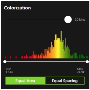
Colorization allows the user to select the number colors to be used to represent the population. The default is 20. It can display as small as two. The option to use Equal Spacing or Equal Area is also available, as shown in Figure 60.
Use the Opacity slider to change the ability to view the background satellite imagery through the population map.
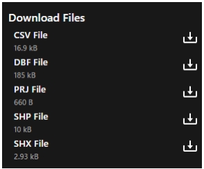
The details of the stand count can be exported. This includes a .csv file with each image listed and the data size associated with that image, as shown in Figure 61. The user can also export the population map as a .shp file.
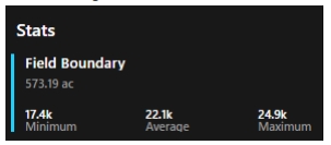
Stats show the field size in acres and the minimum, average, and maximum values for the fields, as shown in Figure 62.
Tassel Count Map
The user can view tassel counts which provide detail on the number of tassels at a location. With tassel data, one can determine a number of items relating to tassels to yield estimation.
Select the field from the field list.
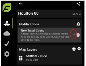
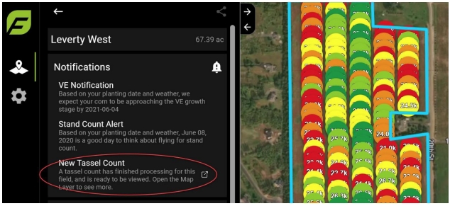
From Notifications, launch the Map Layers in a new window by clicking the launch icon, as shown in Figure 63.
The Tassel Count map displays, as shown in Figure 64.
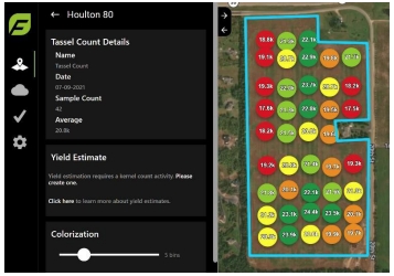
Colorization allows the user to select the number colors to be used to represent the tassels, as shown in Figure 65. The option to use Equal Spacing or Equal Area is also available.
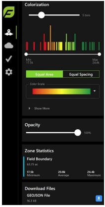
Assign different colors by sliding the Color Scale.
Use the Opacity slider to change the ability to view the background satellite imagery through the NDVI or NDRE image.
From the Download Files area, click the arrow to download the displayed image, which may include GEOJSON files.
Click on a photo dot to view image details, as shown in Figure 66.
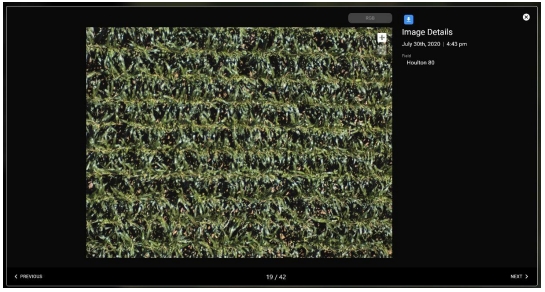
Navigate from one image to another by using Previous and Next arrows at the bottom of the window.
Zoom in for greater detail by clicking the + icon at the top right of the image.
Click the download button at the top of the window to download the image to your desktop.
Kernel Count
The user can enter kernel counts which is used to calculate bushels per acre yield estimate for the field.
After the field was flown and processed for a tassel count, a notification displays that a new tassel count is available for viewing, as shown in Figure 67.
Select Kernel Count from the Activity Type in the New Field Activity area.
Select the date the count occurs.
With an ear of corn in your hand, count the number of rows of kernels the ear has and the number of kernels with in a row. Enter the information, as shown in Figure 68.
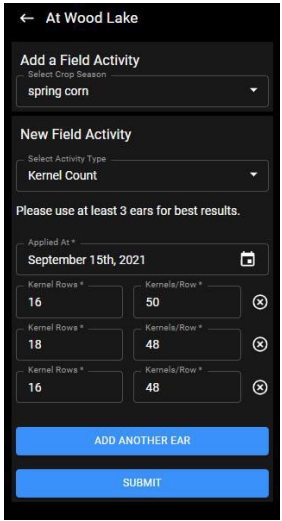
Repeat this for several ears, three or more, to determine a more accurate bushel count.
Click Submit.
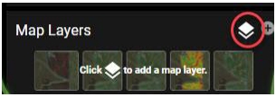
From Map Layers, select the plus layers icon to add the tassel count layer, as shown in Figure 69.
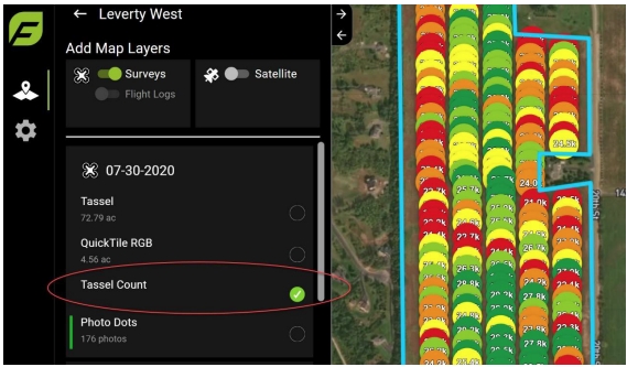
From the Add Map Layers area, scroll to the date of the survey and then select the Tassel Count analytic, as shown in Figure 70.
Click on Tassel Count and it will displays the Tassel Count Details, as shown in Figure 71.
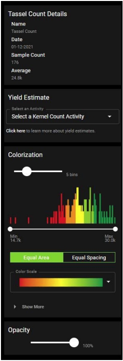
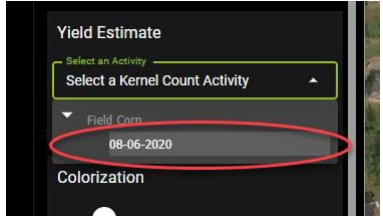
From the Yield Estimate area, select a kernel count activity, as shown in Figure 72.
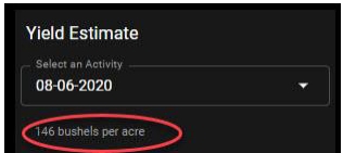
The number of bushels per acre displays in the Yield Estimate area, as shown in Figure 73.
Import Images
The user can import images taken with the Sentera Double 4K and Double 4K Skyport sensors that firmware version 1.0 or higher, and users with the March 2020 firmware update.
Select the field images from the field list to import. See Section 4.3.2 to import images.
![]() Note: Once you import imagery to a field that is not in your home organization, but it is in a partner organization or another part of the hierarchy, you can share the field to yourself, which enables you to see mosaics and tassel counts ordered and produce PDF reports.
Note: Once you import imagery to a field that is not in your home organization, but it is in a partner organization or another part of the hierarchy, you can share the field to yourself, which enables you to see mosaics and tassel counts ordered and produce PDF reports.
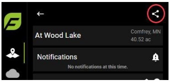
Click the Share icon at the top of the menu, as shown in Figure 74.
Enter the email address to share to, as shown in Figure 75. You can also share the field to yourself, at which point you can see mosaics, tassel counts, and create PDF reports.
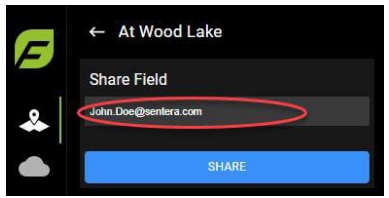
Click Share. A confirmation message will display.
Order Mosaics
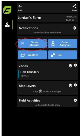
Click Order Mosaics, as shown in Figure 76. The Order Mosaics windows displays.
Select a Survey and Image Types, as shown in Figure 77.
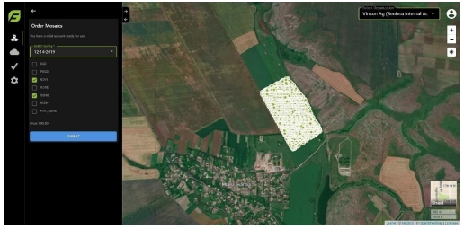
Click Submit to purchase mosaics on the survey. The order will process and an email will be sent when the data is available.
Order Analytics
To order analytics for a field:
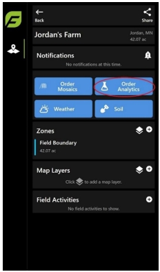
Click Order Analytics, as shown in Figure 78. The Order Analytics windows displays.
Select options from the fields, as shown in Figure 79.
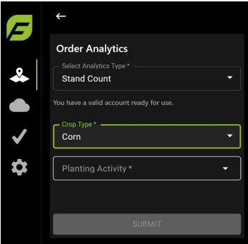
Click Submit to purchase analytics on the survey. The order will process and an email will be sent when the data is available.
Weather Information
The following section describes the weather information area.
Weather Summary
FieldAgent provides aggregation weather data of field, region, country, and overall of Growing Degree Days, Rainfall, and Solar Radiation. Click the cloud icon from the left-hand side of the window, as shown in Figure 80.
![]() Note: Results will display for fields with active crop season data only
Note: Results will display for fields with active crop season data only

Information for the previous 10 years listed includes:
Active Fields: The number of fields reporting weather activity.
Average GDD (°F): Growing Degree Days in Fahrenheit
Average Rainfall (mm): Amount of rainfall in millimeters
Average Solar Radiation (MJ/m²): NASA formula to determine the amount of solar radiation in the zone
Current and Forecasted Weather Conditions
The FieldAgent Web App can provide current, forecasted, and past weather data on each field.
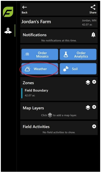
Select a field and then click Weather at the bottom of the menu, as shown in Figure 81. The weather menu displays.
Current and Forcasted Conditions
The following section provides the definitions on the weather conditions section, as shown in Figure 82.
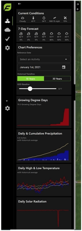
![]() Conditions: Clear, Cloudy, Rain, Snow.
Conditions: Clear, Cloudy, Rain, Snow.
![]() Current Temperature: Ambient temperature.
Current Temperature: Ambient temperature.
![]() Dewpoint: Atmospheric temperature below which water droplets begin to condense, and dew can form.
Dewpoint: Atmospheric temperature below which water droplets begin to condense, and dew can form.
![]() Wind: Listed in direction and speed.
Wind: Listed in direction and speed.
![]() Relative Humidity: Amount of water vapor present in air, listed as a percentage
Relative Humidity: Amount of water vapor present in air, listed as a percentage
Chart
This section describes the various charts available in FieldAgent.
Chart Preferences
Chart Preferences allow the user to set parameters for the crop and the location, such as Imperial or Metric. This section describes how to set the chart preferences:
From the Chart Preferences area, set the Reference Date to the start of the growth date, as shown in Figure 83.
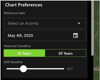
Select the historical trendline option for your preference.
Use the slider bar to set your Growing Degree Days Baseline temperature.
Growing Degree Days Chart
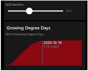
Based on the setting provided in the Chart Preferences, the Growing Degree Days (GDD) area displays. This section describes how to set the GDD.
Slide the GDD Baseline slider to select the temperature, and then move the mouse across the chart to display the date and the calculated GDD, as shown in Figure 84.
Daily & Cumulative Precipitation
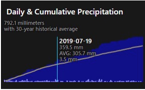
Based on the date set in the Chart Preferences the Precipitation is calculated. This section describes how to set the precipitation.
Move the mouse across the chart to display the Date, Cumulative, Average Cumulative, and Daily Precipitation for the field, as shown in Figure 85. The white line in the following graph shows the 30 Year historical average of precipitation for the location.
Daily High & Low Temperature
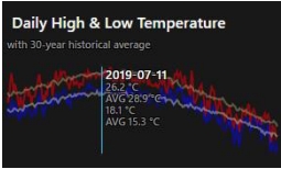
Starting with the reference date, the daily high is in red and the daily low is in blue. The white line in the following graph shows the 30-year average for the high and low temperatures.
Move the mouse across the chart to display the high and low tempatures, as shown in Figure 86.
Daily Solar Radiation
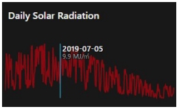
The Daily Solar Radiation window displays the net solar radiation at the crop surface measured in (MJ/m²). This section describes how to view the daily solar radiation.
Move the mouse across the chart to display the daily solar radiation levels, as shown in Figure 87.
Soil
Based on data collected by ISRIC – World Soil Information is available in FieldAgent to help with understanding and making decisions on prescriptions and planting.
Select the field that soil data is needed.
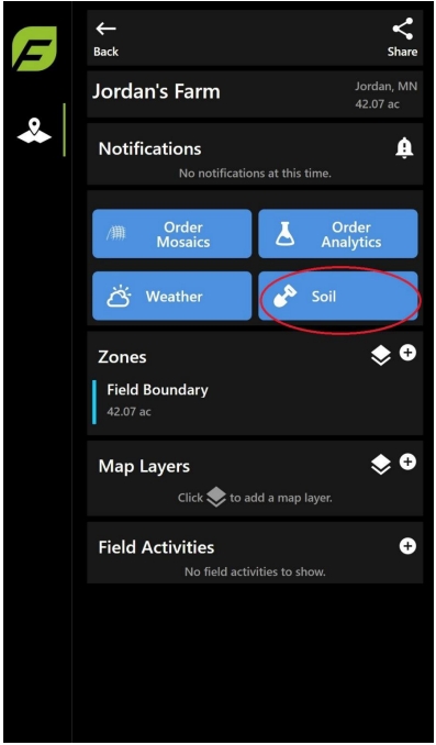
Click on the Soil icon in the menu on the left side of the screen, as shown in Figure 88.
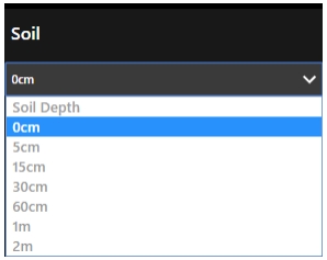
Select the depth of the soil from the drop-down list, as shown in Figure 89.
The details of the soil makeup display, as shown in Figure 90. The value of the soil for this location displays for 0 CM depth.
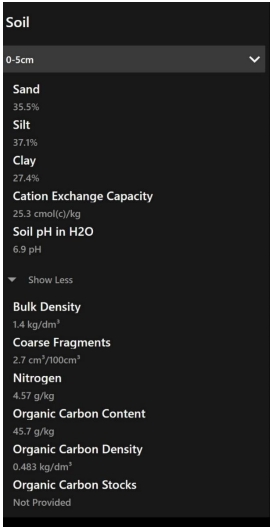
Sand: Percentage of sand in the soil.
Silt: Percentage of silt in the soil.
Clay: Percentage of clay in the soil.
Cation Exchange Capacity: A measure of the soil’s ability to hold positively charged ions. It is an important soil property influencing soil structure stability, nutrient availability, soil pH, and the soil’s reaction to fertilizers and other ameliorants.
Soil pH in H2O: A mixture, by weight, of one part soil to one part distilled H2O to determine soil acidity.
Bulk Density: Weight of soil in a given volume. Soils with a bulk density higher than 1.6 g/cm3 tend to restrict root growth. Bulk density increases with compaction and tends to increase with depth. Sandy soils are more prone to high bulk density.
Coarse Fragments: Particles larger than 2 mm and smaller than 25 cm in diameter.
Nitrogen: The most abundant element in the atmosphere and is usually the most limiting crop nutrient.
Organic Carbon Content: Tends to be concentrated in the topsoil. Topsoil ranges from 0.5 – 3.0 percent organic carbon for most upland soils. Soils with less than 0.5 percent organic carbon are mostly limited to desert areas. Soils containing greater than 12 – 18 percent organic carbon are generally classified as organic soils.
Organic Carbon Density: A percentage of the topsoil 0 – 10 cm.
Organic Carbon Stocks: The quantity of carbon contained in a reservoir or system which has the capacity to accumulate or release carbon.
Field Activities
Field Activities allows the user to document activity in the field-based on seasons. This activity can be planting or irrigation. The information leads directly to how and when the notifications are triggered.
Creating an Activity
To create an activity: Select the field that where the activity will occur.
Click the + icon, as shown in Figure 91, to start an activity.

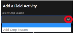
Select the drop-down in Select Crop Season area, and then select Add Crop Season, as shown in Figure 92.
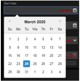
Enter the Start Date and End Date , as shown in Figure 93.
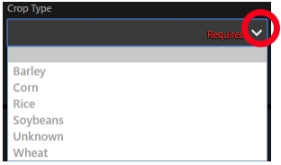
Select a crop type from the dropdown, as shown in Figure 94.
Type a name for the activity, for example, Spring Corn, as shown in Figure 95.

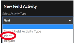
Select an activity from the New Field Activity dropdown, as shown in Figure 96.
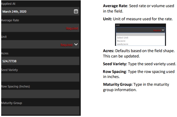
Enter the details in the Plant and Irrigation Details areas, as shown in Figure 97 and Figure 98. The details will vary, depending upon the selected activity.
