> For the complete documentation index, see [llms.txt](https://support.senterasensors.com/home/llms.txt). Markdown versions of documentation pages are available by appending `.md` to page URLs; this page is available as [Markdown](https://support.senterasensors.com/home/rtk-ppk-module/setup-and-installation/rtk-ppk-module-installation/if1200/module-installation-for-65r.md).
# Module Installation for 65R
## Cable Clip
{% stepper %}
{% step %}
### Cable Clips (First Time Installation Only)
Use the alcohol wipe provided with the RTK-PPK kit to prepare the surface of the drone. Clean the area shown.
Once the alcohol dries peal the backing off of the clips and place them as shown. Apply firm pressure to the clip to ensure it bonds well.
{% endstep %}
{% endstepper %}
## Module Installation
{% stepper %}
{% step %}
#### Mount Module to Aircraft
Place the RTK PPK module on the top of the drone. Ensure the forward arrow is facing the sensor. Tighten the screws.
{% endstep %}
{% step %}
#### Install Coax Cable (NON-NTRIP RTK ONLY)
{% hint style="info" %}
This step is only required when operating when the Sentera Ground Radio is used to provide the corrections data. For example when using a base station or laptop for the corrections source.
{% endhint %}
Plug in the coax cable into the side of the RTK PPK module.
{% hint style="warning" %}
When unplugging the coax cable, pull directly outward. Pulling the cable at an angle can cause damage to the cable.
{% endhint %}
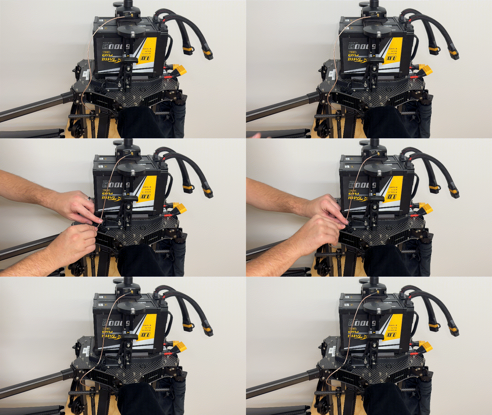
Then connect the antenna mounting bracket to the rail system on the bottom of the drone.
Use the provided hex driver to righten the screw in the bracket and secure the mount.
{% endstep %}
{% step %}
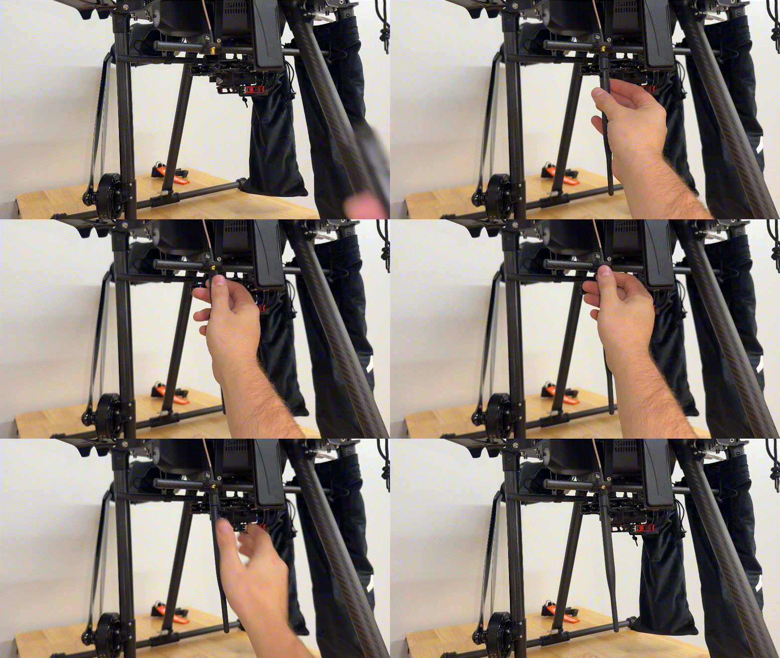
### Install 915Mhz Antenna (NON-NTRIP RTK ONLY)
{% hint style="info" %}
This step is only required when operating when the Sentera Ground Radio is used to provide the corrections data. For example when using a base station or laptop for the corrections source.
{% endhint %}
Screw the antenna onto the connector as show. Point the antenna straight down.
Then secure the coax cable into the cable clips.
{% endstep %}
{% step %}
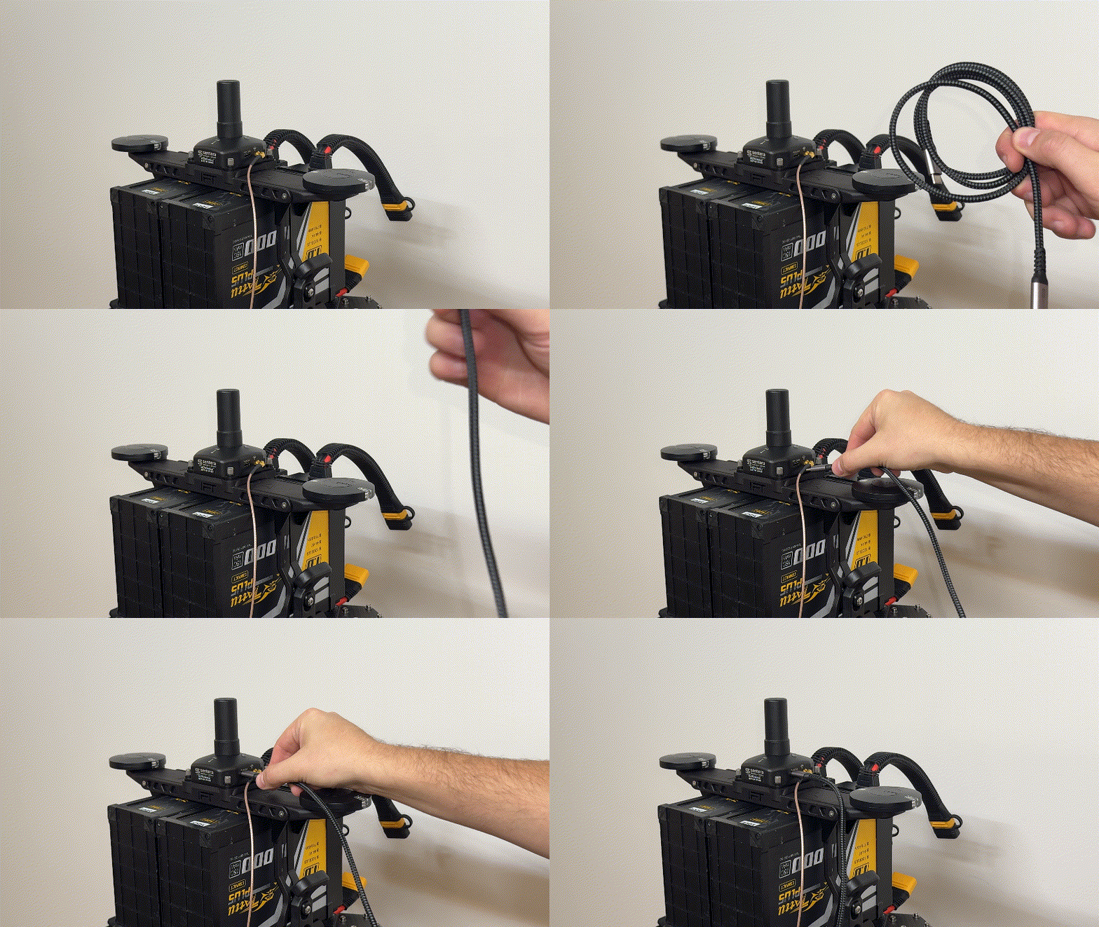
### Install USB-C to USB-C Cable
Plug in the USB-C to USB-C cable into the side of the RTK PPK module.
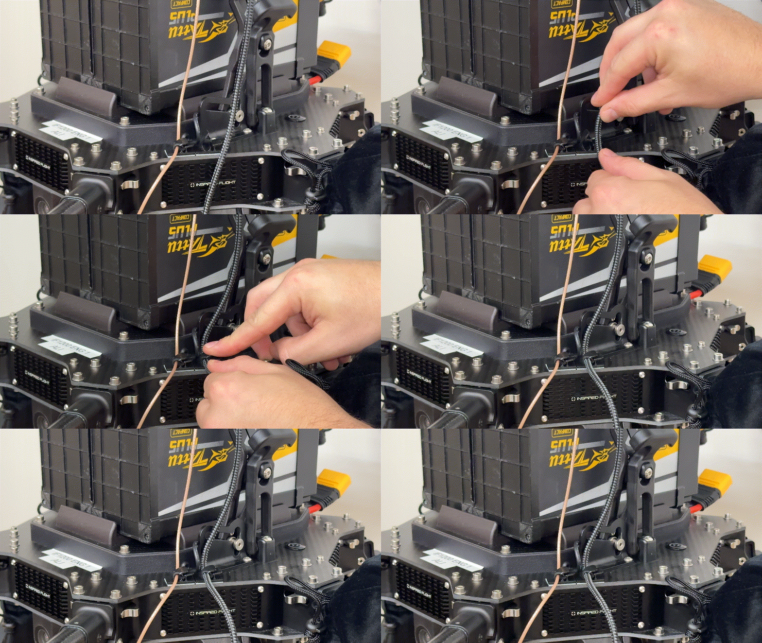
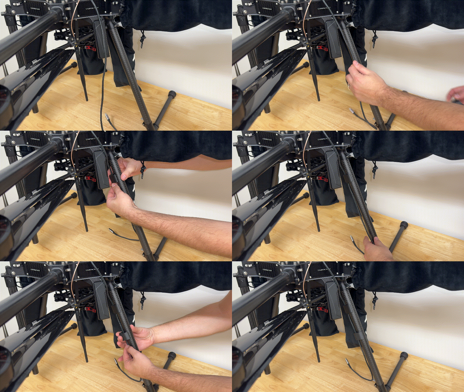
Then secure the cable into the clip.
Next use the leg clips to attach the USB cable to leg of the aircraft. Place one towards the top of the leg and the other about halfway down.
{% endstep %}
{% step %}
### Install The 65R
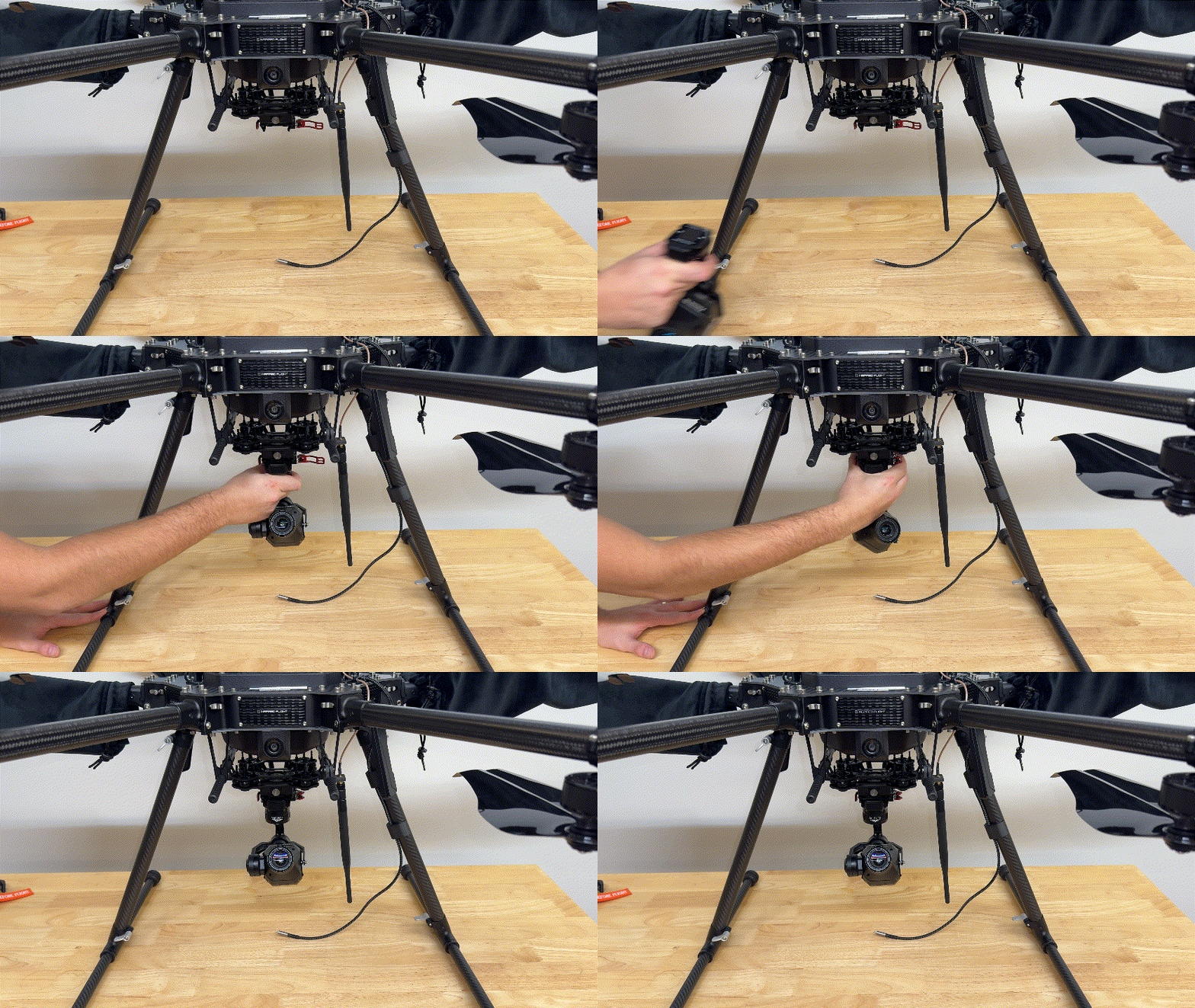
Install the 65R into the payload connector and secure the latch.
{% endstep %}
{% step %}
### Connect Sensor
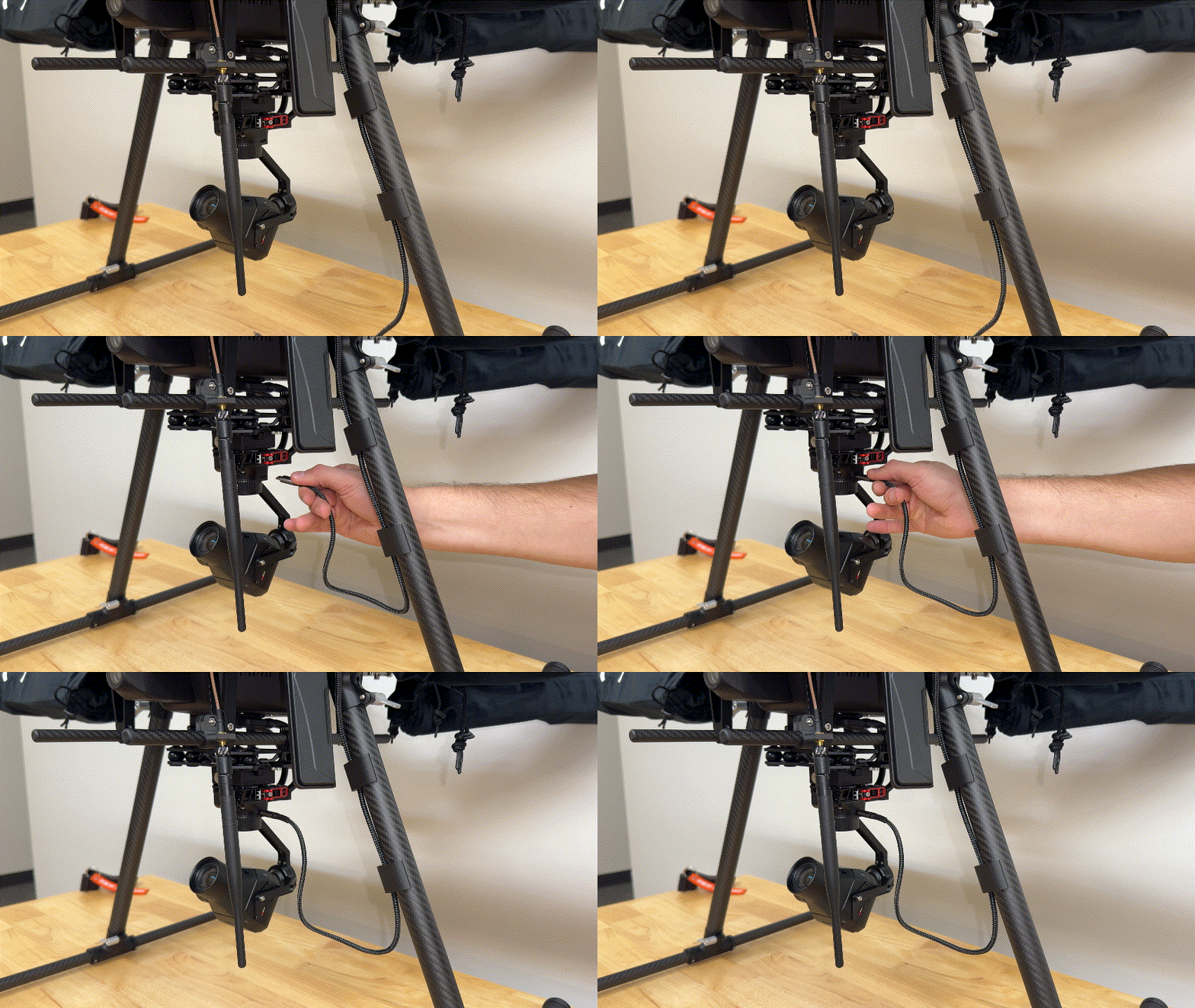
Connect the other end of the USB-C to USB-C cable into the USB-C port on the gimbal.
{% hint style="info" %}
Make sure to use the top port on the gimbal when connecting the USB-C cable.
Do not use the USB-C port on the sensor itself.
{% endhint %}
{% endstep %}
{% endstepper %}
---
# Agent Instructions
This documentation is published with GitBook. GitBook is the documentation platform designed so that both humans and AI agents can read, navigate, and reason over technical content effectively. Learn more at gitbook.com.
## Querying This Documentation
If you need additional information that is not directly available in this page, you can query the documentation dynamically by asking a question.
Perform an HTTP GET request on the current page URL with the `ask` query parameter, and the optional `goal` query parameter:
```
GET https://support.senterasensors.com/home/rtk-ppk-module/setup-and-installation/rtk-ppk-module-installation/if1200/module-installation-for-65r.md?ask=&goal=
```
`ask` is the immediate question: it should be specific, self-contained, and written in natural language.
`goal` is optional and describes the broader end goal you are ultimately trying to accomplish on behalf of the user. GitBook uses it to tailor the answer towards what is most useful for that goal.
The response will contain a direct answer to the question and relevant excerpts and sources from the documentation.
Use this mechanism when the answer is not explicitly present in the current page, you need clarification or additional context, or you want to retrieve related documentation sections.